We are planning to make publish on lapiegatrice.it about theory of press brakes in IT and DE languages. We would like to present this article also in English, probably will be helpful for somebody. This article was already published on our website about the tooling. Now we are making it better and more detailed.
Concept of term – press brake
Press brake is the main industrial machine to perform the technological operations as plate and sheet metal bending. Today, in sheet metal industry the stand-alone press brake is the general unit for bending of pre-fabricated parts (after cut or punching) to make the shape of the final product. If we are talking about the typical sheet metal workshop before press brake there are cutting operations (cutting with laser, waterjet or plasma cutting machine or punching with punching press) and after are operations to finalize the final product as welding, painting and assembly operations.
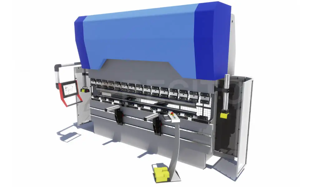
Model of typical CNC press brake with frontal supports and safety system
Press brake machines have been in the industry for more than 100 years. Press brake bending technology was developed in the same period with new achievements in precision, quality, and control. Moreover, for nearly the last 70–80 years, the general construction and the main principle of work of the press brake machine have not changed.
Construction and functionality
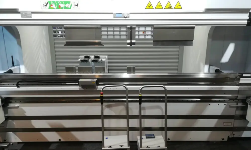
In the market, usually the construction of the press brake is the C-frame construction. It could be explained as follows: 2 shoulder side plates with the table (the term “bed” is also used) between them, the beam or traverse as the moveable unit to add the force and to perform the bend, the power unit that is responsible for initiating the force, press brake tools installed according to the bending task, a back gauge for part positioning operations, and the units for control of movements and positioning.
The other modern and known construction of press brakes is “O-frame construction,” but in general, it is an additional development of the C-frame with table and shoulders in one construction. This frame has additional advantages (usually in marketing materials) based on its high rigidity, which should lead to better precision. But it will work in reality only if the O frame really is done as one metal-piece structure. Otherwise, it will be just an additional composition of welded C-frame.
The functionality of the press brake is equal to the classic press. But the construction allows for the deformation of sheet metal for a longer length, which means that forced and controlled movement works on the sides of the beam.
Wikipedia and other sources provide a lot of general mixed information about press brakes, but we would like to make a more theoretical article about types according to the way of working and possibilities. Anyway, our classification is not official. Different manufacturers provide their own specifications, details, and differences.
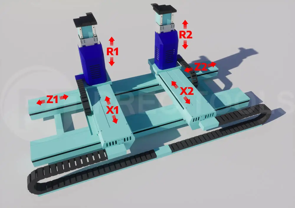
Typical movements of press brake (axis explanation)
Each movement of the press brake is controlled by a power unit called the axis. Each movement of the press brake or axis has both software (CNC-control) and hardware control (power unit installation).
- Y1 / Y2 (this means both sides of the press brake, Y single only for small machines) – the main movement of the beam (usually down movement). Driven by a mechanical system, hydraulic, servo-electric, pneumatic etc. Y1 and Y2 could be left and right hydraulic cylinders or left and right servo drives.
- X – approach of press brake back gauge (horizontal movement). Could be X1 / X2 with separate control of each side of the back gauge.
- R – vertical movement of back gauge. Could be R1 / R2 with separate control of each column of the back gauge.
- V (V1) – crowning (deflection compensation system) if operated with numerical control.
- Z – the movement of fingers of the back gauge along the machine length. Could be Z1 / Z2 with the separate control of each finger.
Additional movements that could be in automatic installation:
- 1 axis/2 axis sheet follower movements (as an additional unit)
- Movements for automatic tooling change
- Movements of robot/gantry system to load-unload the pieces into the working zone and position where it is necessary
Typology of press brakes
Layout and press brake dimensions
- Compact (small machines with the length of bending up to 1200–1500 mm) usually for small parts, low tonnage and small dimensions to install in workshop. We would like to note that small machines (and on the market are available constructions even with 300–500 length) could have the forced movement not on sides and directly at center. The small length of bending allows to not have any deflection of beam on sides.
- Typical standard machines from 1500 up to 6000 mm with different tonnage. For example the most typical machine for the market which is installed in many workshops is 3000-3200 mm with 100-120 tons of force.
- Big machines usually with high tonnage and big length applications from 6000 till 12 meters or more.
Power unit to obtain the force and the power the beam
- Manual handled (table and console machines with the hand levers to obtain the force)
- Mechanical with the flywheel (old and rare constructions)
- Pneumatic (also old and rare constructions, popular in years 70–80s)
- Hydraulic (powered by the hydraulic cylinders — the general concept of press brake used worldwide today)
- Servo-hydraulic or Hybrid (powered by hydraulic system and servodrive)
- Electric (modern technology to obtain the force and movements with the servodrive without the usage of hydraulics)
In addition it is necessary to tell that this terminology used to identify only the power unit for force and beam movement but not the movement of the backgauge which is usually manual or servo-electric in all the ways.
We can note, in addition, press brake units. This is not typically a press brake but a bending unit to be installed in other equipment, for example, a garage press, to perform the bending based on the force of the main equipment.
Control unit / type of the control
- Manual controlled. All movements and stops are adjusted, performed, and fixed with mechanical stoppers, hand wheels or limits. Press brake doesn’t have any digital control. The bending and movement usually performed by hand lever. Backgauge is manual or just stopper, no any automatic movements.
- Digital numerical controlled with simple panels or input boards with possibilities to input values for main strokes (and first to control the travel of the press brake beam and the horizontal approach of the backgauge (axis X if presented). It could be called also as semi-automatic as NC or simple controller machines.
- CNC controlled. Press brake machine has the CNC control installed as an industrial computer. It controls in digital all main functions and strokes, possibility of interfaces for programming, program storages, various cycles, control of more than 2 axis and auxiliary units control, simulation possibilities etc.
Force / tonnage of press brake
- Low tonnage (usually up to 30–40 tons)
- Medium tonnage (50–120 tons)
- High tonnage (120–320 tons or more)
- Heavy tonnage (more than 320 tons up to any values. On the market there are supplies of machines up to 2200 tons in one machine or more)
Together with the length tonnage is the main important parameter of the press brake. The available tonnage determines possibilities for the maximum thickness of the bended metal and availability to work with different materials and bends.
Stroke of the beam
- Upstroke (the stroke is performed by the beam on top side — the standard concept for all main machines worldwide, the table is idle and non-moveable)
- Downstroke (the non-moveable top side of the machine and the table is moving towards to the upper beam. This configuration is very rare, we know only one low-tonnage machines active manufacturer with this concept)
Clamping system press brakes / system of press brake tools
This classification means that the clamping system is pre-installed on the factory. User himself cannot change it in easy way without service technicians:
- Press brakes with Promecam — Euro system (all manufacturers from Europe, mainly Asia, North and South America)
- Press brakes with American style system (the main system for North America)
- Press brakes with Trumpf-WILA or LVD similar system (with safety- or quick- clicks and buttons)
- Press brakes with LVD- old system; Beyeler-Bystronic , Colgar, EHT, Colly-Ajial, Durmazlar, country-specified machines etc. (clamping systems specified and used by the specific manufacturers)
We will specify more in our new articles about bending tooling system. It is the most important to determine and to choose the correct press brake tools for your machine. Different systems means different geometry of the connection parts for your tools. Tools of other press brake systems possible to use only through adaptors..
Press brake construction
- Standard typical machine
- Tandem (two standard or non-standard machines installed together. They have synchronization of the movement to achieve the total bending length for 2 machines, for example 6 meters installation based on 2 press brakes each 3000 mm)
- Tridem (as tandem but 3 machines installed together)
Tandems and tridems are usually controlled with one control to perform the synchronized operation of 2/3 machines. They perform synchronized the main beam movement, stop, and position of the back gauge. Even if there are several CNCs presented (each for the machine) the program is duplicated to run in all.
Why to use such configuration? To tell the absolute truth, it is much easier for manufacturers to make 3000 mm than 6000 mm machines as single versions. The longer construction will require more studies, more heavy parts based on bigger deflection, more rigidity, etc.
For sure, there are a lot of differences between the tandem 3-meter machine and the stand-alone 6-meter machine, for example, the absence of the shoulders in the middle for the possibility to proceed with bigger parts. But for a lot of applications, for example, light poles, tandem construction could be enough. And this solution will be much cheaper than a stand-alone machine for the full length.
Opening / daylight of press brake
- Standard as the standard opening / daylight planned for manufacturer as standard construction
- Extended opening for bigger daylight and extended stroke for deep applications.
Daylight or opening of the press brake is a very important parameter. It helps to understand how deep the could be parts for the bending and how tall could be the bending tools that could be installed on the press brake itself.
Press brake automation
- Stand-alone machine as one single unit
- Standard machine with the partial automation — for example equipment of sheet followers for big or heavy parts
- Robotic bending cell which means to replace the operator with the robot to load and unload parts and move according to the necessary positioning
- Complex automation systems with robots or other devices to perform not only the movements of part but also to change the press brake in automatic mode if necessary and connected with automatic tooling storages systems as well as automatic transfer of pieces to other machine tools (punching machine, laser cutting, pressing etc.)
- Automatic systems with gantry-type systems (the same as robot but the other concept of automation)
Safety rules
- CE-certified with laser or light guards
- CE-certified with low working speed without the additional safety devices
- Non CE-certified
Safety rules in each country could be different. The main point is that a press brake is a dangerous piece of equipment with the risk of pressing or crushing the hands of the operator if they are between the tools during the moment of bending. That is why according to the laws press brakes should have the safety equipment to detect if any obstacle is presented during the process of bending (i.e. hands) to stop the machine movement immediately. Otherwise, the press brake should work only at the lower speed to have enough time to remove the hands out of the working zone.
This post is also published on @Medium