Please note – this is not commercial article and we would like to write a history of development of press brakes as the independent author. So we use some other info and publications with reference links for general purposes. The header picture is from here
We tried to make the best informative article based on public information and we can assure you this is the best information you can find on the internet today about the history of press brake developments. We studied a lot of sources and documents, webpages of various manufacturers, and tried to bring the best. We hope you will find it interesting and useful.
Bending technology
We have already been told a lot of times that the traditional technology of bending which is used in press brakes today has been well known almost more than 70 years.
All right, that time it was not the traditional press brake machine but mainly presses with force with top and bottom bending tooling installed similar to the punch and die which is used on bending machines today. For sure works were much more simple and bending punch geometry was mainly the straight one to perform the simple bend.
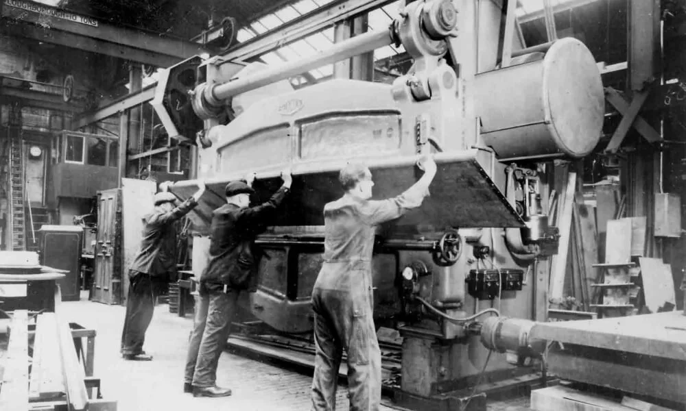
The photo from here. According to the source it is dated by 1957 year. It is an interesting picture because you can have radius bending here (several strokes) and die with 2-V openings so you can rotate it to install another V-groove. This seems the big hydraulic press to perform the classic action of press brake – to bend the sheet metal with the movement of the punch.
First of all the photo exposed the principle of the working of the press brake – after so many years it is completely the same as we know it now with the modern machine tools.
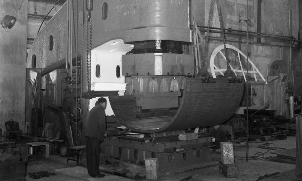
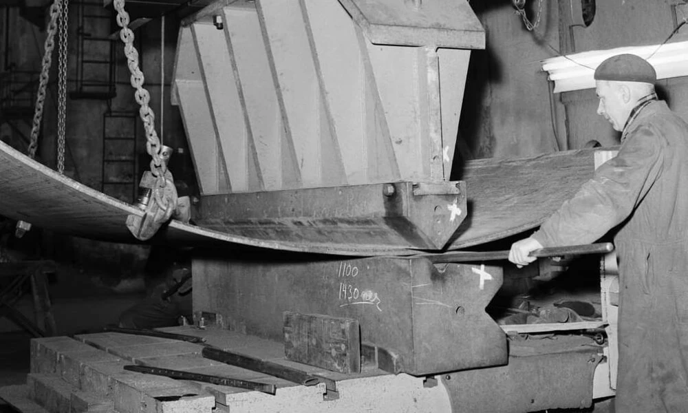
The photo from here. It seems that this way of bending was quite popular with huge hydraulic presses and the advantage of this is the possibility to obtain a really huge force to bend the thick plates. Without a doubt the main limit and the difference of the construction of the classic press brake is the limit of possible length for bending – it is quite small. Meanwhile, it is well known that in WW2 even tank head parts were made with this technology.
Press brake as we know it today
When the classic press brake construction was invented?
When the classic press brake construction was invented? First, we can say that the world a hundred years ago was not so global, and new developments in one part of the world were not a reason that the same will be shared immediately with other parts of the world.
If we are talking about the USA – here is the link that informed that Pacific Press company started to produce press brakes during WW2 which means the early forties. Internet knows everything but it is hard to find something about the real history of press brakes so we don’t know who invented the first classic machine with 2 shoulders for the length of several meters like the construction that is widely used today.
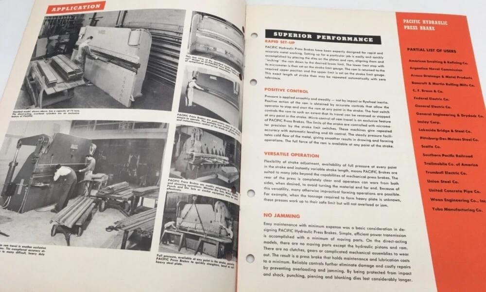
The picture took from here. When we wrote this article the material was at the eBay sale.
And if we just look at the brochure we can see that it is not the advertisement for a prototype or the machine tool developed yesterday. This looks like serious serial production i.e. available models, various installations, complete machine data and already performed tests, studies, and positive results at the customer’s sites for the comfort commercial sales. So I mean, if the brochure is dated 1948 there are at least several years before this when the machine was developed.
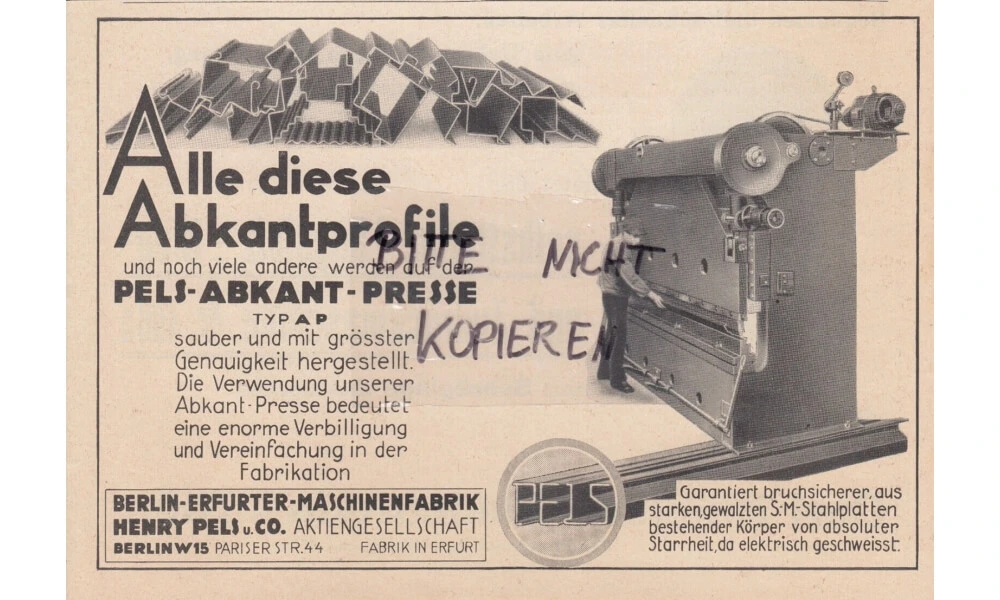
The picture took from here.
In this advertisement for the East German company Erfurt is very interesting that according to the information of the seller, the material is dated by 1936. And we also see here the product is ready for sale, not the prototype and fresh development. Erfurt factory was very active in the production of machine tools till the early 90s and still, a lot of machines are in production.
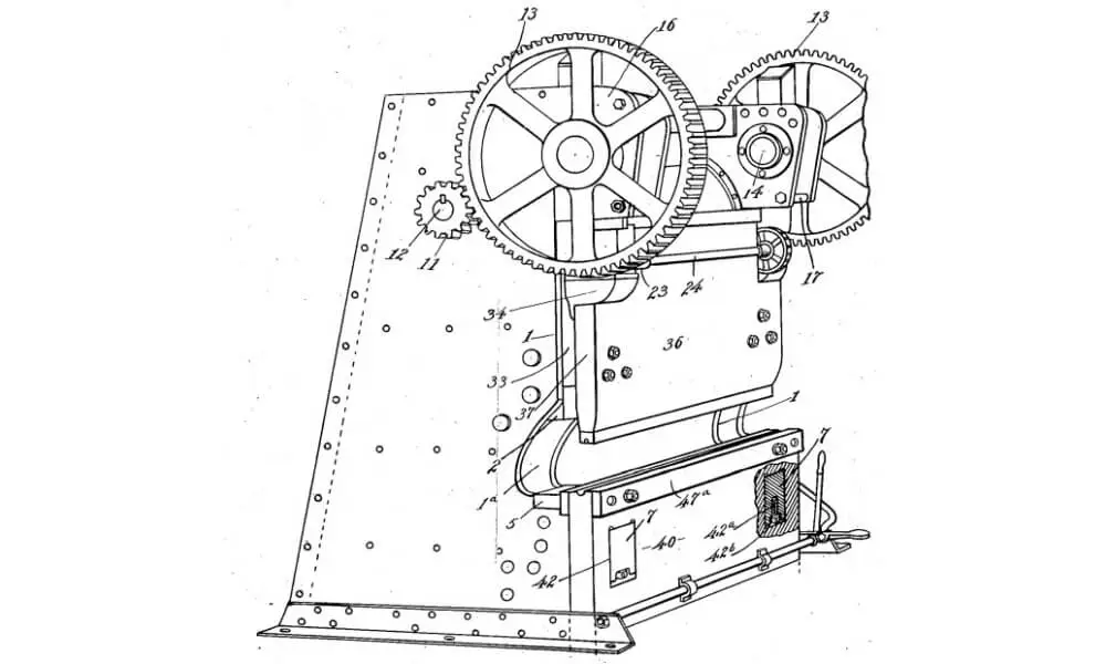
We thought that for us it will be impossible to find more old sources and in general in the past this part of article was other. But we made one more study and we found patent US1618825A which called just “Press brake” and made on 1924, describe the simple construction of mechanical press brake so nearly 100 years before by person connected with company Cincinnati. Probably this is the earliest source we were able to find.
About patents there are really very interesting things about some press brake units and functions, for example US3214955A of 1961. We never encountered such things but very useful for research – the lower tooling (die) there was made as a round shaft with grooves and rotation with fixation by the level.
During the making and editing of this article, we studied a lot of published texts on the Internet. In all American sources, the history of the press brake is connected also to the invention of the cornice brake in 1882. It is true and not true.
First, thanks to Google, we found this patent and it is dated 1887.
Second, the principle of cornice brake is a swivel lower beam. And it is important that it is the main and the same principle as today for “sheet metal folding machine”. In general, the purpose is the same – bending of sheet metal, but the principle of working is completely other, and possibilities (and a lot of time applications) are different. So cornice brake is not the historical grandfather of the press brake but a completely different type of equipment.
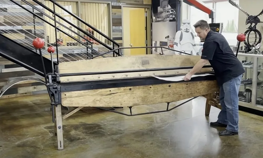
Screen from video of original cornice brake manufactured ca. 1895 is demonstrated in work by the company Revolution machine tools
Timeline of history of press brake
So based on what we found we can consider the following timeline:
1887 – patent of cornice brake (as we told you before we doubt that we can directly connect it to the press brake) but we can connect it to the “bending machine”
1924 – first press brake patent for classical press brake construction with mechanical power
1925 – … – different developments in construction as development and invention in various tonnage and length, method of tooling use and change, inventions in control of deflection and crowning function of press brake
1960 – 1970 – development of press brakes with ram (beam) movement hydraulically driven. Actual patent for hydraulic press brake in 1968
1960 – Constant growing of tonnages and length for press brakes. On the Internet, we can find the real machine made by Cincinnati in 1974 with 1500 tons of force / 10 meters. Mainly for a lot of even big companies 1500-1600 tons are the most possible limits for press brake construction even today. About the biggest possible press brake, we can see 2 actual sources: 5500 tons press brake by company Ursviken, Sweden, and 6000 tons press brake by company Baykal, Turkey.
1970 – 1980 – first CNC press brakes developed. It is not the same control as we can see it today, without the actual display but with digital function and control of travel. Actual patent for computerized numerical control press brake in 1977.
1981 – … – the start of developments of safety devices for press brakes. In 1981 the first patent for a safety device for press brake to provide the safety to operator based on the photoelectric sensor.
1989 – … – Patent and development of the first electro-mechanical force units for press brakes. The start of the era for a new generation of press brakes without hydraulic systems driven by servomotors.
During the XX century, there were a lot of interesting inventions, development, and research of various ways to transmit power, power units, tooling use and functionality, various tool clamps, various bending tool systems, and methods and functions of press brake control. To tell the truth, by the end of the century the press brake came the same as we can see it now but without the powerful PC on board and graphic functions in CNC control.
Classic construction of press brake
So finally. The bending is possible with the hydraulic press, it was made more than 70 years ago and is possible even today and used somewhere as one more function to make small length parts as brackets.
But the real work with sheet metal required the bending with a big length and a more technological solution than the standard press which is mainly high tonnage, complicated to install the tools, and quite expensive equipment for the factories. So the invention led to the classical press brake construction – the machine with 2 shoulders and a beam installed on 2 sides to perform the parallel travel up and down. Such construction allows to go with more length, easier access to the working zone, and parallelity of the beam from the sides. And hydraulic system is mainly used as an easy and good source to provide the necessary force for the press brake. Mechanical (clutch) press brakes have been presented in the past and somewhere available as new even now (for example in India) but do not have a big amount on the worldwide market.
So let us speak about the general view and the construction of modern press brake which has been well-known for more than 50 years. We already made an article about press brake typology in the past but maybe now we can renew something of it.
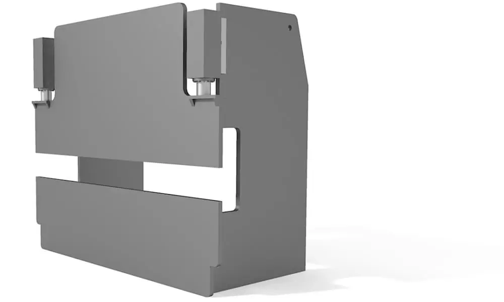
Typical frame construction of press brake (3d model render)
The welded bed is connected with 2 shoulders from both sides of the machine. Mainly the table (low part) is fixed and non-movable (there were some machines in the past with downstroke so with a movable table but it is better to ignore it because their percentage on the market is very low). The upper part – traverse is moveable and goes up and down according to the request of the operator. It is driven with 2 hydraulic cylinders from the sides of the machine.
There are some variations – for example, only one forcing unit at the middle (hydraulic or servo drive) for small length or hydraulic cylinders are replaced with electric drives. Press brake works with the proper bending tools: dies are installed on the table. Punches are installed on the beam to go down and to perform the bend. To tell the truth, the base of kinematics and movements is a quite simple construction with one stroke – up and down.
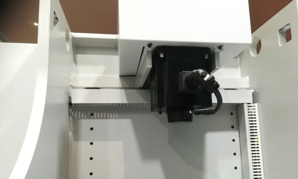
The photo of back of compact CNC press brake with the use of servo motor for driven power for upper beam and stroke.
A small note because it affected the market in the 1950s-1960s mainly in Europe. The small company “Promecam” which was later purchased by Japan company AMADA in the mid-80s was the real leader in press brake production these years and Promecam in a lot of talks was even just the synonym of press brake. Their first main presses (which we can consider as “key products” because they were sold in thousands of units in the world) were upstroke which means that the upper beam was completely fixed and the table with the installed die was moveable with all power units of the machine placed at the bottom.
Promecam machines are widely used in production even though they are incredibly old and have been at work for dozens of years. Promecam was also the first manufacturer (based on the materials we have found) who made the promotions not only of press brakes as machine tools for sale but for the solutions of bending, different ways, different applications, and different tools to explain the widest range of possibilities which could be interested in the potential customers.
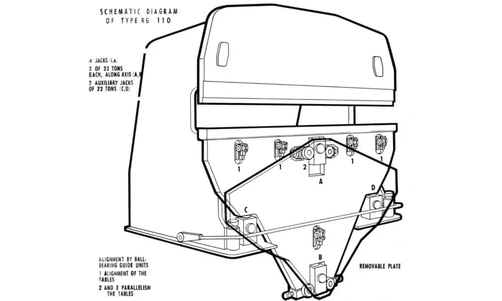
The picture from here illustrates kinematic function of press brake active stroke for model Promecam RG
Digital controls for press brakes
Now we are starting the story by explaining the complete press brake machines’ evolution and differences. As we told before the machine is simple with one movement so on the machine today and on the machine 70 years before the movement was the same. The difference is only with regulations and how it was performed. The final distance between the beam and table in old machines was regulated with mechanical jacks, screws, stoppers, then with hydraulic pistons, etc.
Together with the becoming of the era of digitalization numerical controls were invented and adapted to the regulation of the position of the ram through the numerical panel which allows precise movement and comfort working for the operator. So, the installation of digital controls, digital outputs, and inputs, digital guides with the reading of the actual position of the beam made a big jump to the machine which we see normally today in production worldwide.
The back gauge is one of the additional and most important elements of the construction. What does the back gauge of the press brake? According to the requirements it is positioned with the finger stop where you should place and position of the part. So back gauge makes the operator the assistance for precise part positioning. Can the bend be performed without a back gauge? Yes. Can the bend be performed with the use of a manual back gauge like a simple metal fixator? Yes. So back gauge makes nothing for the bend itself. But it allows the positioning of the part BEFORE bend so the bending will be precise, exactly on the line where it should be. So like the main function of the press brake (beam movement to perform the bend) back gauge provides not only additional functionality but provides the availability of quick and precise bending operations.
When press brakes in the world became to be “numerically controlled”?
At first, we are talking about beam digital input to get the real positioning and the system to compare it with the desired position. According to the patents database, we can refer to the patent N US3874205A for Hurco Manufacturing Co Inc. company. It is hard to understand who was first but the timing is quite realistic: the 70s were the years when a lot of types of fabrication and metalworking machines were developed with new systems of numerical controls. But for sure as we said it is quite hard to search and to find the real picture and mainly this is ignored in all books about press breaks because they are written by engineers and not detectives or searches for historical passes.
Anyway it is interesting to see – we found an ad for sale of 75 Ton x 10′ Chicago Dreis & Krump 810-C Press Brake, 1972. As you can see the machine has already a numerical panel and numerical control for the back gauge as well.
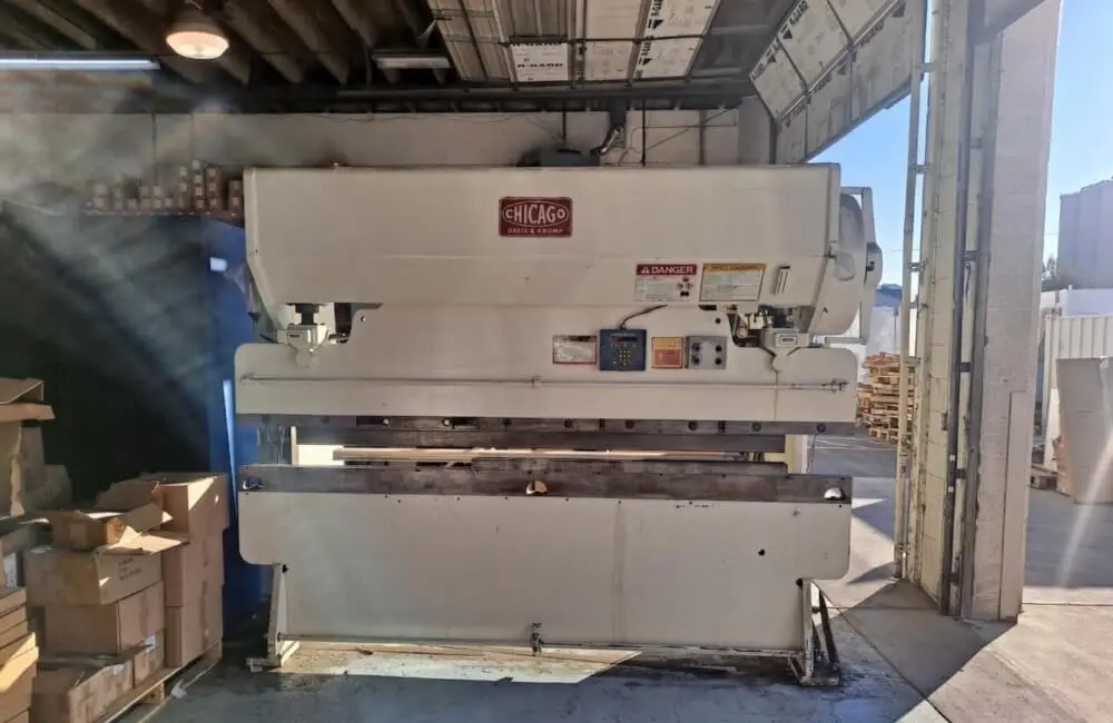
Picture of press brake from website of Revelation Machinery
It is interesting to note the fact that even historical machines are “touchable” today and still on the market, even after 30-40 years of work. There are many reasons and some of them are simple construction, simple service, no difference in bending (if we are not talking about real precise parts and a big bending cycle with a lot of steps), and for sure the money if we are talking about a high tonnage machine. A new big tonnage or big length press brake machine costs a lot so maybe it is easier to save investments and to care for old machines already installed in the factory.
We will continue this topic in the second part so keep in touch!